ASME Section VIII, Division 2, Part 5 - Fatigue from Cyclic Loading

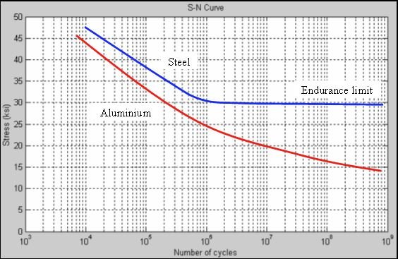
Fatigue is a failure mode that occurs due to cyclic loads. The process involves the initiation and propagation of cracks that grow and eventually fracture. Fatigue data is experimentally obtained from standardized samples of different materials and a plot of alternating stress vs number of cycles to failure is obtained. The graph below shows S-N curves for steel and aluminum. (Note: logarithmic scales are often used so one needs to read the graph carefully)


The code indicates the following to address fatigue.

Screening Criteria (to see if fatigue analysis is required)

  1. Past Experience

  2. Method A

  3. Method B

Fatigue Assessment Methods

  1. Elastic Stress Analysis and Equivalent Stresses

  2. Elastic Plastic Stress Analysis and Equivalent Strains

  3. Welds - Elastic Analysis and Structural Stress

Ratcheting Assessment

  1. Elastic Analysis

  2. Simplified Elastic Plastic Analysis

  3. Thermal Stress

  4. Elastic Plastic Analysis

Ratcheting or cyclic creep is when plastic deformation accumulates due to cyclic mechanical or thermal stress.

ASME Section VIII, Division 2, Part 5 - Local Failure Mode - Brittle Failure of Ductile Material

What precisely does the term "local failure" refer to in the ASME code and how do we evaluate this failure mode? Basically, a ductile material (such as steel) can fail in a brittle manner and we need to check this possibility.

Cauchy Stress Tensor

This stress tensor is a key concept in the linear theory of elasticity and is used for stress analysis of material bodies involving small deformations. The general 9 component stress tensor can be broken down into two other tensors, the hydrostatic stress tensor and the deviatoric stress tensor. The hydrostatic tensor is addresses changes in volume while the deviatoric tensor is concerned with changes in shape as shown below.


The term sigma m in the hydrostatic stress state (which can be either pure tension or pure compression) causes a elastic volume change but no shape change. In addition, sigma m will not affect the yield stress of the material but will affect the value of the fracture strain. Fracture strain is the capability of a material to tolerate deformation before fracture.

Local Failure Methods

Elastic Analysis

The code requires comparing the sum of the three principal stresses to a maximum allowable stress limit.

Elastic Plastic Analysis

The code requires comparing the sum of equivalent plastic strain and forming strain to a limiting triaxial strain.

ASME Section VIII, Division 2, Part 5 - Buckling Failure Mode (Geometric Instability)

Buckling is a failure mode which requires compressive stresses in a structure where a large increase in deformation occurs with a small in crease in load. It is a failure mode since the buckled structure can no longer support the loads. Three analysis methods are available.

Elastic Buckling

A buckling analysis is performed using elastic stress analysis without any geometric non linearities to determine prestress in the component with a minimum design factor and loading combinations.

Elastic Plastic Buckling

A buckling analysis is performed using elastic plastic stress analysis with geometric non linearities to determine prestress in the component with a minimum design factor and loading combinations.

Collapse Analysis

A collapse analysis can be performed using elastic or plastic material behavior and includes geometric imperfections where the design factor is built in to the load combinations.

Conclusion

Buckling can be a catastrophic failure mode that must be checked per the ASME code.

ASME Section VIII, Division 2, Part 5 - Plastic Collapse Failure Mode

Three numerical analysis methods are available and current editions of the code should be consulted for further details.

Elastic Stress Method

In this method, equivalent stresses (von Mises) are calculated using an elastic analysis, classified into categories and compared to allowable values. The different categories are: general primary membrane, local primary membrane and local primary membrane plus bending.

Limit Load Method

This method involves determining a lower bound to the limit load of a component. The allowable load involves applying design factors to the limit load such that the onset of plastic collapse will not occur.

The code consists of using scaled loads and an elastic perfectly plastic material model. Acceptability of the design is based on numerical convergence for the scaled loads.

Elastic Plastic

The collapse load is determined from both the deformation characteristics of the component and the applied loading. The allowable load is established by applying design factors to the plastic collapse load. The material model is elastic plastic and scaled loads are used. The analysis includes non linear geometry and convergence must be obtained for the scaled loads for the design to be considered compliant.

Conclusion

It is not always straight forward deciding which method to use and an experienced engineer can help. It is important to note that any of the three methods are acceptable by ASME code and a component design is considered acceptable if any of the three analysis methods are satisfied.

ASME Section VIII, Division 2, Part 5 - Failure Modes

Design by Analysis (DBA) indicates that 4 failure modes must be checked when applying the code to pressure vessels or other covered equipment. The 4 modes are:

  1. Plastic Collapse

  2. Local Failure

  3. Buckling Failure

  4. Cyclic Loading

Each mode involves calculating stresses and then comparing these stresses to acceptable values. In addition, each mode allows for the use of different methods to establish that the failure mode of interest passes code requirements. Future articles will discuss these modes and methods in more detail.